How We Design: The Precision Dividers
Woodworkers and watchmakers have been complaining about the same divider problems for decades. Here's why we decided to fix it — and how.
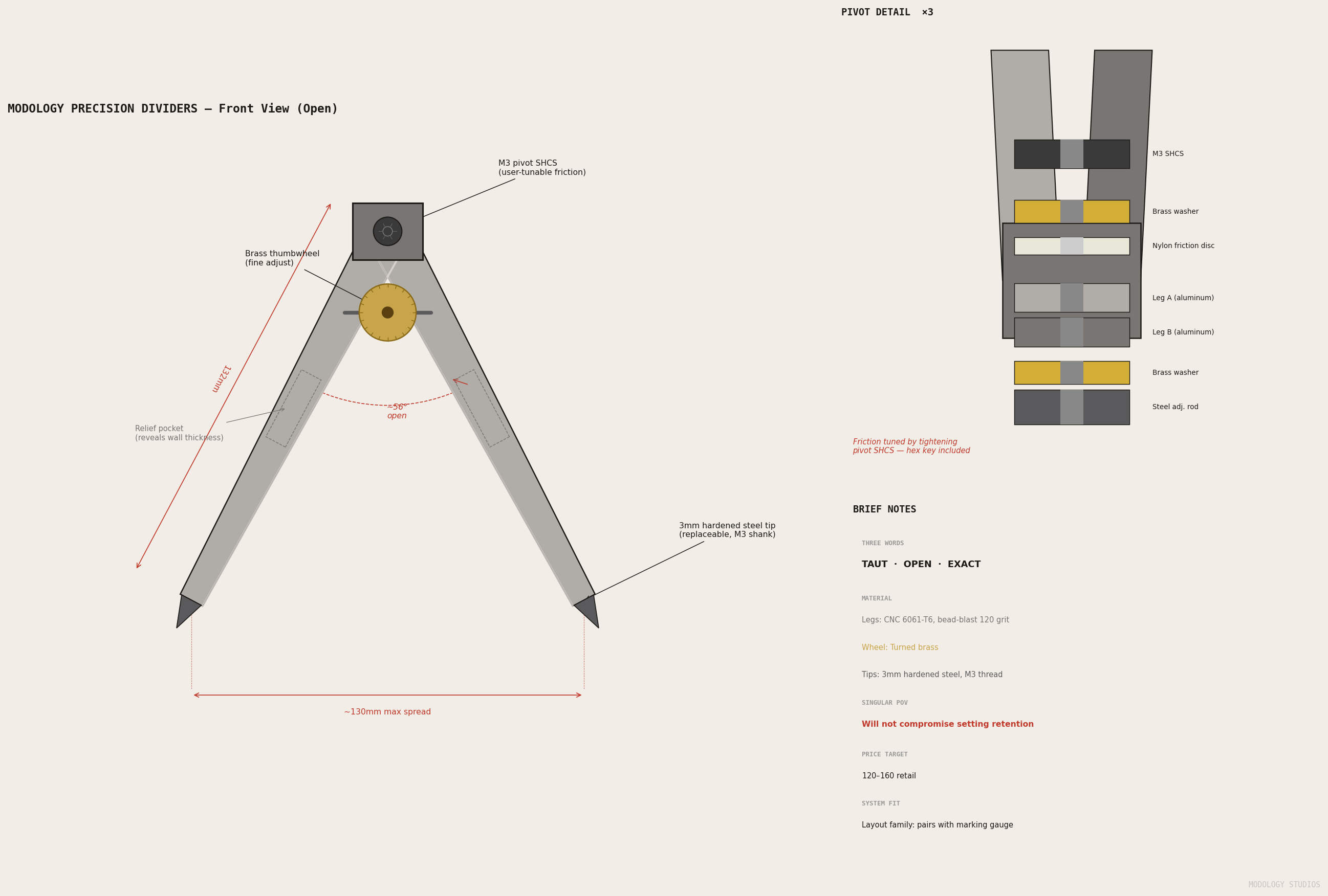
Most tool companies start with a product. We start with a complaint.
For the Modology Precision Dividers, we started with a lot of them.
The Problem
Dividers — also called wing compasses — are one of the oldest layout tools in existence. A pivot at the top, two legs spreading at a controlled angle, hardened tips at the bottom. You set the spread to a measurement, lift the tool, and transfer it to your work: step off a board’s width, scribe an arc, find the center of a dowel. The geometry is simple. The execution, apparently, is not.
Go looking in woodworking forums, watchmaking communities, and maker spaces and you’ll find the same complaints surfacing over and over:
“The set screw on my dividers stripped the first week. Now I have to clamp it with my thumb while I work, which defeats the entire point.”
“I have three pairs. All of them drift if I put any pressure on the tip. I’ve shimmed the pivot on two of them. The third one lives in a drawer.”
“The tips on cheap dividers are soft. After a dozen uses on hardwood they’re rounded enough that you’re not scribing a line, you’re drawing a groove.”
“Why does every set of dividers under $200 feel like it was designed by someone who has never actually used dividers?”
These aren’t complaints about price. They’re complaints about function. The pivot drifts. The adjustment strips. The tips dull or wobble in their bores. The instrument that exists technically works — you can transfer a measurement with it — but you’re fighting the tool the entire time.
The version that just holds doesn’t seem to exist at a price that isn’t “antique Starrett.”
Why We Made It
We make tools for people who work with their hands and care about what’s in them. Our marking gauge, stop block, and marking knife all came from the same place: a specific frustration that the market had failed to resolve.
The divider problem is clean. It has three distinct failure modes, each with a known engineering solution. Nobody had put all three solutions into one instrument at a price accessible to the people who actually need it.
That’s a product.
The harder question was whether it was a Modology product. Our bar is strict: the form has to be photogenic, the manufacturing path has to be clear, and the design has to resolve tensions that can’t be sketched on a napkin. Dividers clear all three. Two tapered aluminum legs spread at a controlled angle with a brass thumbwheel at the adjustment point is a form that makes immediate sense the moment you see it — and the geometry that makes it actually work is harder than it looks.
The Design Process
Three Words Before Any Geometry
We don’t start with CAD. We start with three words.
For the dividers: TAUT · OPEN · EXACT.
These words aren’t descriptors — they’re a decision filter. Every design choice gets tested against them. The three words have to be in tension with each other, or they’re not doing any work.
TAUT and OPEN fight each other. A taut instrument wants to be closed, compressed, resolved. An open form wants spread, negative space, room to breathe. EXACT sits between them and sets the standard: whatever the form resolves into, it has to be precise.
The tension between TAUT and OPEN is why the open negative space between the legs is a design feature, not a byproduct. The V-shape of the spread IS the measurement — visible, geometric, honest.
The Competing Constraints
If a product can be sketched on a napkin without constraint, it’s not ready to design. The form has to emerge from tensions that resist easy resolution.
For the Precision Dividers, those tensions were:
Rigidity vs. adjustability. The legs need to hold a set spread under the force of scribing. They also need to be adjustable with one hand, one thumb, one motion. A rigid instrument doesn’t adjust. A loose one doesn’t hold. The resolution is a nylon friction disc at the pivot — user-tunable resistance that can be set stiff enough to lock and loose enough to step off deliberately.
Material weight vs. balance. Aluminum is the right material for the legs — it’s stiff, machinable, and bead-blasts to the right surface texture. But aluminum is light, and a lightweight pivot block drifts under repeated scribing pressure. Brass at the thumbwheel adds mass where mass belongs: at the adjustment point, which is also the center of gravity. The brass doesn’t just look right — it changes how the instrument feels in hand.
Tip precision vs. replaceability. A scribed tip needs to be hard — harder than most woods. Hardened steel is the answer. But hardened steel tips are consumables; they dull and eventually break. The geometry had to accommodate M3 threaded shanks and countersunk bores so tips can be changed without touching the instrument’s calibrated geometry. The legs are permanent. The tips are not.
Gesture Before CAD
Before the geometry was parametric, it was charcoal.
The gestural line for this product is a taut bow — two arms under load, held open by the tension of the measurement between them. Think of a compass held at full spread just before it touches paper: that moment of potential, of precision held in physical equilibrium.
We drew thirty versions of that gesture before committing to a proportional split: the pivot block occupies the top third, the leg bodies the lower two-thirds. Equal halves would have looked ambiguous. The 2:1 ratio gives the eye somewhere to go first, and settles the form into something that reads as intentional rather than arbitrary.
The Geometry
The legs are 132mm from pivot centre to tip socket, tapering from 14mm wide at the pivot to 8mm at the tip. Every terminal edge is chamfered at 45°. Relief pockets on the non-reference faces reveal the aluminum wall depth — structure made visible rather than hidden. The form doesn’t pretend to be a solid block.
The pivot runs an M3 SHCS through the block. The nylon friction disc between the legs sets the resistance. Stiff enough to hold a setting through several working strokes. Loose enough to step off the spread in one deliberate motion with the thumb. Tunable with a hex key — tighten as the disc wears.
The thumbwheel is brass: 18mm diameter, 7.5mm wide, seated on its own adjustment rod that runs between the legs. The brass isn’t decorative — it’s the right density for a part that needs to be found by touch without looking at the instrument. It also oxidizes naturally in the recesses of the knurl, which makes the texture more legible over time rather than less.
The tips are M3×0.5 threaded shanks, countersunk entry into the leg bores. Hardened tool steel. They thread in by hand and are retained by friction — replace them in under a minute, no tools required.
The Iconic Test
We apply a three-part test to every product before it ships:
- Recognizable — is the form distinctive enough to identify at fifty yards?
- Greater truth — does the design embody a value larger than the object itself?
- New standard — does it make the previous approach look compromised?
The dividers pass all three. The open V with a brass thumbwheel at the apex is recognizable in silhouette — there’s nothing else in a tool chest that reads the same way. The greater truth is exactness: this is what a measuring instrument looks like when nothing is approximate, when every design decision is load-bearing. And if you’ve ever used a divider with a slipping set screw, you already know what the new standard means.
What’s Next
The geometry is complete and we’re currently prototyping. We’ll share renders and updates as they come — if you want to follow along, reach out through the contact page.
Coming soon.